A Case Study for Correcting Non-Compliant Data Center Airflow Patterns16 min read

Every data center industry standard and best practice compilation specifies the importance of having all rack-mounted equipment breathe from front to rear. The minor exception is the telco standard, which merely recommends that all equipment receive and move air in the same direction. Not only is the exclusive use of front-to-rear breathing equipment important, but a reasonable case can be made that deploying such equipment is the single most important airflow management practice for a healthy data center. After all, consider for a moment the relationship between the air movement direction of IT equipment and the other tactics, strategies, and disciplines that comprise the basic principles and practices of standards, best practice guidelines, white papers, textbooks, and countless conference presentations and certification curricula:
Blanking panels without exclusive front-to-rear breathing equipment could prevent bypass air from entering the rear of the cabinet or the sides of the cabinet to mix with exhaust air, thereby preventin the creation of an environment more conducive to the survival of non-compliant airflow equipment ingesting from those hot areas.
Cable access cut-out floor grommets without exclusive front-to-rear breathing equipment could prevent bypass air from entering the rear of the cabinet or the sides of the cabinet to mix with exhaust air and likewise prevent the creation of a hot and cold mixture of air for equipment pulling air in from the sides or rears of cabinets.
Hot aisle – cold aisle separation, by definition, would not exist without exclusive front-to-rear breathing equipment.
Controlling supply temperatures by feedback from the equipment air in-take points would not be practical with 15-20˚F differences in input temperatures, depending on the airflow protocol direction and volume of bypass.
Changing from a return thermostat temperature control to a supply control temperature will not be effective when some equipment will be ingesting input air mostly from the return side of the data center row layout.
Reducing fan speeds may not be practical when some amount of bypass air needs to be produced to drop the temperature in the “hot” aisle to support non-standard breathing equipment.
Raising supply air temperatures may be disastrous when some equipment may be ingesting air that is input temperature plus equipment temperature rise (ΔT), or even exhaust temperature plus ΔT.
In addition to installing design-intent non-compliant airflow equipment, we have exacerbated the situation by willfully and intentionally installing some switch equipment backward, particularly in top-of-rack switch deployments. However, this strange behavior does not make us criminals – it merely makes us sensitive to the demands of accessing switch ports for connecting our networks. Fortunately, the switch manufacturers have been paying attention to our dilemma, and many switches are now available with buyer-specifiable front-to-rear or rear-to-front internal fan trays. Nevertheless, while these sophisticated design options make our work easier, we still have details that need attending to in order to fully realize the benefits of the new switches with fan direction options. An Upsite Technologies® customer has graciously shared data from two different data centers to provide real-world examples of the benefits of incorporating one of their SwitchFix accessories with corrected fan direction switches.
The basic problem can be illustrated by the example in Figure 1 below. One of the reasons we always talk about the importance of installing blanking panels in all unused rack spaces is while the overall flow is from front-to-rear, all the space in a server rack behind the front equipment mounting rails and/or side air dams is going to be defined by the equipment exhaust air temperature. While that air is being pushed backward out of the cabinet, all airflow is always going to be from higher pressure to lower pressure, and if that air has access to any equipment fan intakes, that is where it will head. In the case of top-of-rack switches with port-side exhaust, the in-takes may still reside in an area affected by the server exhaust temperatures.
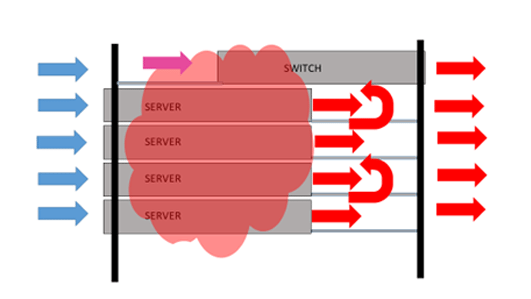
Figure 2, on the other hand, shows the same equipment deployment but with the top-of-rack switch in-take protected by the Upsite Technologies SwitchFix, resulting in only cold aisle air being pulled into the switch.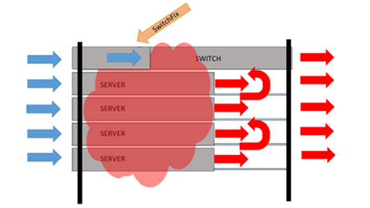
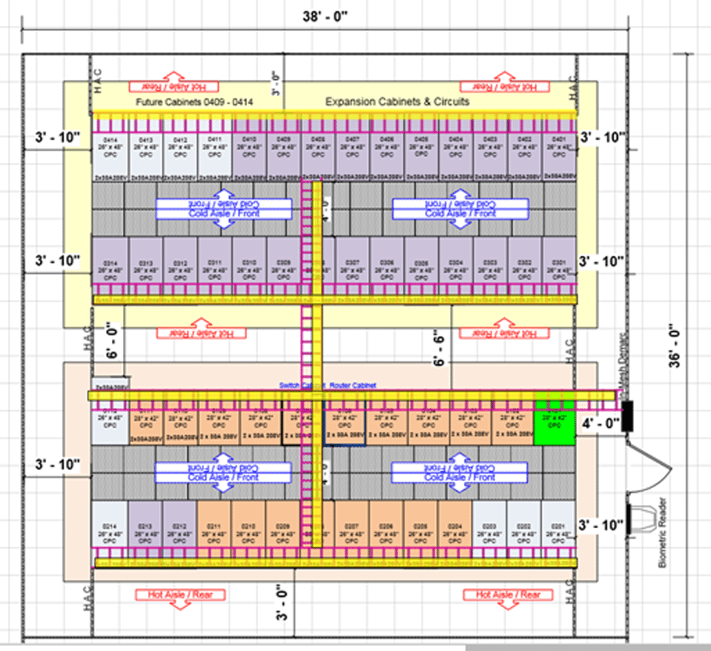
A global e-commerce company with data centers in several U.S and international locations deployed Cisco 3048 switches in top-of-rack configurations and added the appropriate SwitchFix accessories in two of those data centers. Figure 3 represents one of the rooms from the data collection and is generally representative of all the spaces. The data center is on a raised floor, and hot aisles are partially contained with end-of-aisle doors.
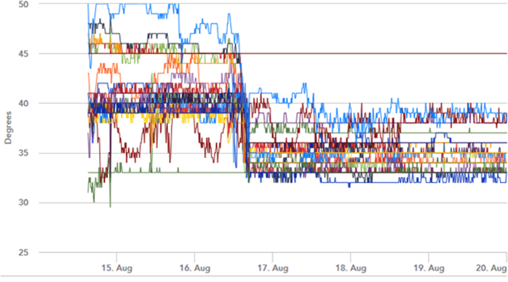
The data center operator collected switch temperatures via SNMP traps before and after the installation of SwitchFix air management accessories to bridge the open space between the fan tray/power supply intake face of the switch and the cold aisle in front of the cabinet. Figure 4 captures all the data points from one cage and is representative of both analyzed rooms. In fact, differences are all in fractions of degrees. Occasional outliers hit on different days since the deployments were some three months apart. The graphic representations of the temperature data are striking.
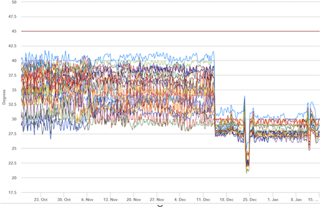
In one cage there were 25 SNMP traps that were pinged every 270 minutes. The average switch temperature before installing the SwitchFix was 94.8˚F (34.9˚C), and the average temperature after installing the SwitchFix was 82.8˚F (28.2˚C). The average improvement was a 12˚F (6.7˚C) decrease in switch temperature, ranging from two units with a 2.9˚F (1.6˚C) improvement up to one unit with a 21.6˚F (12˚C) improvement.
Much more important than averages, however, is the reduction in maximum switch temperatures. The highest average maximum temperature was 104.9˚F (40.5˚C), which was 0.5˚C above the manufacturer’s environmental specification and 4.5˚C below the data center alarm threshold. With a standard deviation around 0.54 for that sensor, there were five readings above 106˚F (41.1˚C). After installation of the SwitchFix units, the highest switch temperature was 93˚F (33.9˚C).
Based on the line graph data in Figure 4, we can see that the occasional readings above 90˚F (32.2˚C) are what we would call statistical outliers and could be attributed to influences such as an end-of-aisle containment door left open for longer than simple ingress or egress or perhaps removing a blanking panel during a service operation. That is worth noting because any resulting operating temperature adjustments could accommodate the outliers or ignore them, depending on the operator’s aggressiveness in pursuing energy savings. The reader is invited to re-visit “Airflow Management Considerations for a New Data Center, Part2: Server Performance versus Inlet Temperature” and “Airflow Management Considerations for a New Data Center, Part 6: Server Reliability versus Inlet Temperature,” in the Upsite Technologies blog library for insights into the effect of brief excursions into some of these higher temperature realms.
Just for the sake of taking a conservative approach here, I will assume we want to plan for accommodating all historical outlier data points. With that approach, the reduced range of temperatures produced by applying SwitchFixes to all the top-of-rack Cisco 3048 switches in the studied data centers would allow for increasing data center supply temperature by 10˚F — with some headroom remaining between maximum recorded temperatures and maximum allowable operating temperature from the manufacturer’s user documentation. With no free cooling, such a supply temperature increase, in a data center fully enabled with variable drives on everything, would produce a .038 – .1 reduction in PUE. With free cooling in the equation, any further PUE reduction could vary from incremental to dramatic, depending on the location of the data center and the baseline starting point for supply temperature.
Sometimes, as in the data reported in Figure 5 below, adding the SwitchFix can actually save equipment from living (and dying) in the area above temperature alarm thresholds, well beyond any recognized allowable boundaries, particularly in the absence of other standard airflow management best practices.
Certainly, in the event of a steady sequence of alarms and warnings, a deployment of SwitchFix airflow management accessories is in order. However, the data center does not need to be in crisis to benefit from harmonizing switches to the airflow management patterns of the overall space. It is not only good for the switches, but can also be a significant benefit to the overall health of the data center ecosystem and the bottom line impact of PUE improvements.

Ian Seaton
Data Center Consultant
Let's keep in touch!
Airflow Management Awareness Month
Free Informative webinars every Tuesday in June.
0 Comments