The Less Commonly Known Delta Ts in Data Center Cooling17 min read

The other two important ΔTs – the temperature differential from IT equipment exhaust to cooling unit return intake and from cooling unit supply to IT equipment intake – will account for unexpected differences between the IT equipment ΔT and cooling equipment ΔT. In an ideal data center, the ΔT across the IT equipment would be the same as the ΔT across the cooling coils or cooling source and there would be zero ΔT between the IT exhaust and the cooling return intake or between the cooling supply and IT equipment intake; however, most data centers will exhibit these differences. Understanding the sources of these differences can help mitigate cooling and inefficiency problems and return a data center to mechanical health.
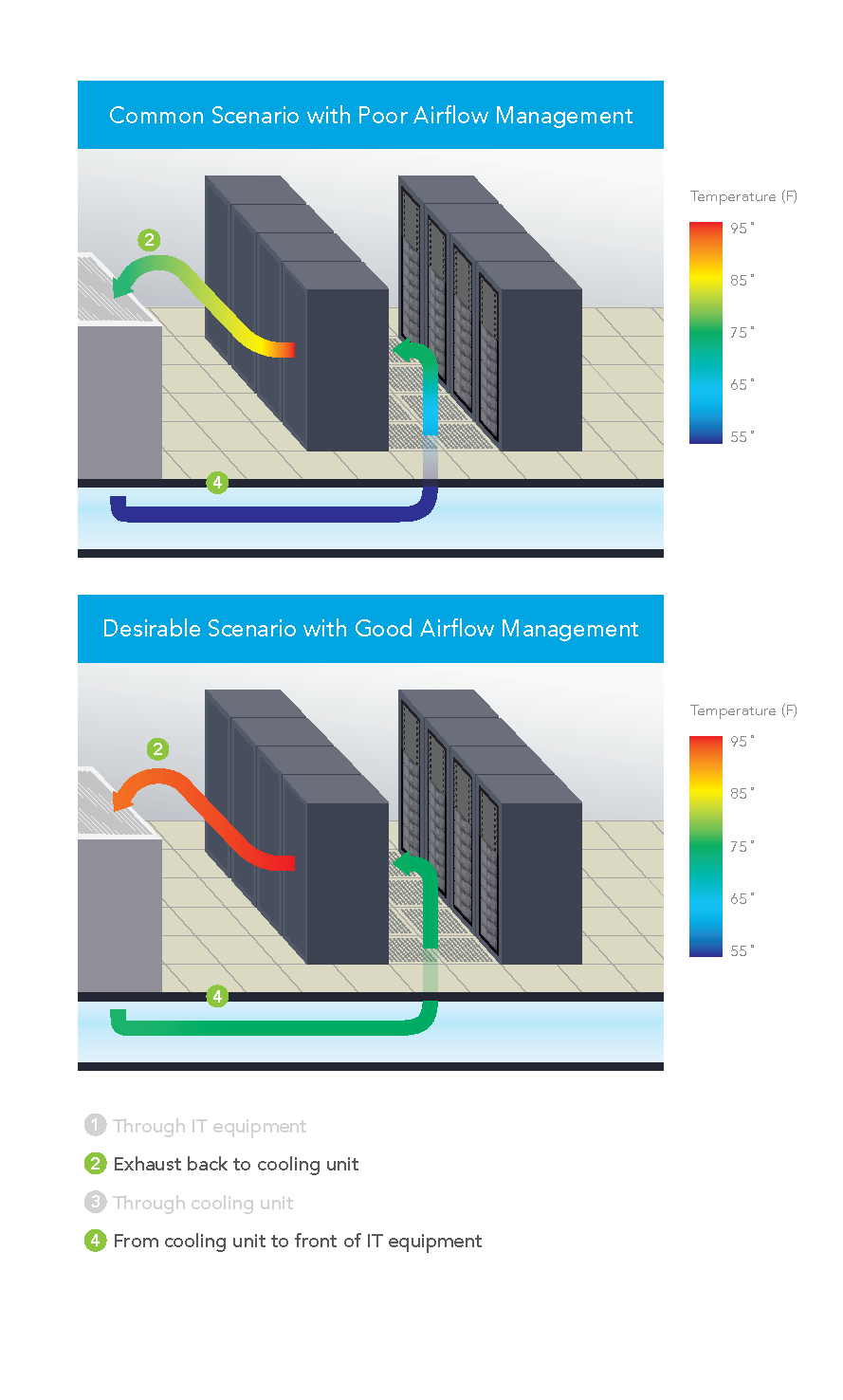
From Cooling Unit to Front of IT Equipment
It is actually somewhat surprising that the ΔT between the cooling unit supply output and the server inlet is not on many radars. After all, if you have 55˚F being supplied, which is fairly typical, that is over 5˚F below the recommended minimum temperature for data processing equipment per the ASHRAE environmental guidelines. That low temperature is not a problem because by the time it reaches the IT equipment it is typically going to be in the 70’s, or even higher. What happens? Sometimes that supply air can warm up even before it enters the room from under the floor. For example, perforated floor tiles located too close to CRAHs can actually draw warm air into the under floor space by virtue of low pressure created by high velocity supply air – the well-known Venturi effect. That path for heating the underfloor air does not have to depend on the air velocity close to cooling units. Underfloor obstructions can create vortices which can result in low pressure pockets which can pull air from out of the room into the underfloor space, mixing with the supply air and thereby increasing the temperature before it evacuates through perforated tiles into the data center. Then, once the supply air enters the computer room, it is still subject to conditions which can further increase the temperature. If there are openings in the server racks, either open rack mount spaces or unsealed areas around the perimeter of the equipment mounting area, some of the server waste air can leak back into the cold aisle and affect the temperature of the supply air. Because of this contamination, we frequently see warmer temperatures the higher in the rack we get. Exacerbating this internal re-circulation by not receiving an adequate flow through isolated floor tiles due to low pressure zones under the floor or simply due to inadequate total available airflow volume, we can see hot air re-circulation over the tops of cabinets or around the ends of cabinet rows. The ultimate result from increasing the supply temperature along the vertical plane in front of the server rack is that the server rack inlet to outlet ΔT can be significantly higher than the equipment ΔT. For example, the temperature rise through all the servers might be 20˚F, but the inlet temperature at the bottom of the rack might be 60˚ and the outlet at the top, rear of the cabinet might be 95˚F, for a rack ΔT of 35˚, or 175% of the actual IT load.
Exhaust Back to Cooling Unit
Conversely, in most data centers today the ΔT from the servers back to the cooling source is negative; that is to say, the temperature of the return air tends to decrease after it is exhausted from the IT equipment on its return path to be re-cooled. The dynamic in this situation is very straightforward: excess cooling air is bypassing the data center heat load and returning to the cooling units, reducing the temperature of the return air along the way. There can be several causes of such bypass airflow. Improperly located perforated floor tiles (the boss gets too hot in the hot aisle) can cause cool air to bypass heat load. Large underfloor pressure differentials can result in high pressure zones that pump volumes of air into a cold aisle or portion of cold aisles in excess of the demand indicated by the intake fans of the associated IT equipment. Unsealed cable access holes in tiles located toward the rear of server racks will result in cold air directly joining the exhaust air inside the back of the server rack. This source of bypass airflow can be a little tricky when you are trouble shooting cooling efficiency issues by monitoring ΔTs, because it can mask the true IT equipment ΔT. The simple rule of thumb here is if there are unsealed floor cut-outs in the rear of server racks, that will result in bypass and those holes should be plugged up before any other monitoring or corrective action steps are taken.
Remedial Considerations
In most situations, the optimum efficiency in the data center will be achieved when there is minimal difference between the supply air temperature and the server inlet temperature, minimal difference between the IT equipment ΔT and the cooling coil ΔT, and the supply temperature can, as a result, be elevated to a temperature approximating the maximum specified upper threshold for the space. Monitoring all four ΔTs can provide valuable assistance for dialing in the data center to meet this optimum performance level. Any server inlet temperature that is more than 5˚F above the supply temperature being produced by cooling units means that there is hot air re-circulation caused either by open pathways between hot and cold aisle, inside or around the server racks, or there is an inadequate flow zone that may require CFD analysis to determine source of pressure variations under the floor. If the return air intake of the cooling units is more than 5˚F lower than the exhaust temperature from the IT equipment, then there is a bypass airflow problem. Areas to check include improperly placed floor tiles, unsealed floor openings, or simply excess airflow being delivered into the room.
These 5˚F guidelines for calibrating ΔTs are merely suggestions that will help move a data center into the top 20% of efficiently and effectively performing data centers. However, the goal, particularly if free cooling is available to the data center, should be to get those differentials between the server and the cooling unit return intake and between the supply and the server intake as close to zero as possible. That alignment will result in a better harmonization between expenses made for cooling and true cooling work required, and will also increase opportunities for more free cooling hours, if free cooling is part of the total design. In conclusion, then, I’d say your goal should be to disprove my opening statement and create a space in which there is truly only one ΔT.
Real-time monitoring, data-driven optimization.
Immersive software, innovative sensors and expert thermal services to monitor,
manage, and maximize the power and cooling infrastructure for critical
data center environments.
Real-time monitoring, data-driven optimization.
Immersive software, innovative sensors and expert thermal services to monitor, manage, and maximize the power and cooling infrastructure for critical data center environments.

0 Comments