The 4 Delta T’s of Data Center Cooling: What You’re Missing21 min read

When was the last time you had a conversation with anyone trying to sell you something for your data center and Delta T (ΔT) didn’t pop up at least a couple times? This bit of jargon is so pervasive in our industry that no one is surprised to hear “Delta T” as a slick rock band parody of the Beatle’s “Let It Be” at conference parties and hospitality suites. It’s just as natural. Nevertheless, there is a little more to ΔT than is typically understood.
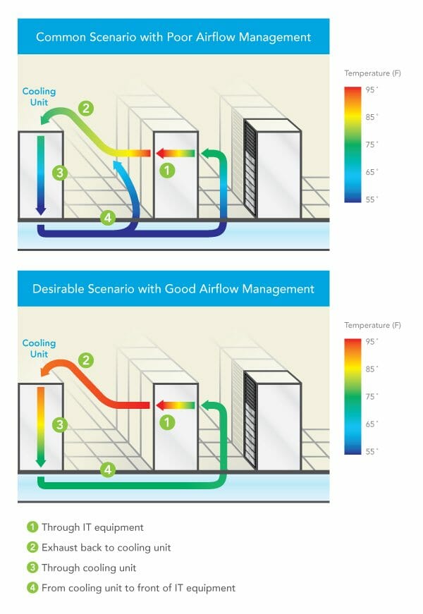
For example, there is not just THE ΔT and there are not even just two ΔT’s in the data center. As a matter of fact, there are four different ΔT’s which contribute to the health of the data center. Two of these temperature differentials are frequently considered as a single metric: the temperature rise of air as it passes through IT equipment, picking up and removing the heat produced within that equipment and the temperature differential across the cooling equipment cooling coils, or the difference between supply and return air temperatures. Frequently these two ΔT’s are discussed as “The ΔT,” but there are good reasons for considering them separately and monitoring how they may actually differ. In fact, the other two important ΔT’s – the temperature differential from IT equipment exhaust to cooling unit return intake and from cooling unit supply to IT equipment intake – will account for unexpected differences between the IT equipment ΔT and cooling equipment ΔT. In an ideal data center, the ΔT across the IT equipment would be the same as the ΔT across the cooling coils or cooling source and there would be zero ΔT between the IT exhaust and the cooling return intake or between the cooling supply and IT equipment intake; however, most data centers will exhibit these differences. Understanding the sources of these differences can help mitigate cooling and inefficiency problems and return a data center to mechanical health.

Figure 1: Maps of the four ΔT’s
The More Commonly Known Delta T’s
Through IT Equipment
Typically ΔT is discussed in our industry as a single metric or phenomena and, depending on who is doing the talking, that single metric is based on the temperature drop across the cooling equipment or the temperature rise across the IT equipment. There are many reasons why these two values may be different, but those reasons will generally fall into two categories – the return air to the cooling units is being cooled by bypass airflow or it is being warmed due to hot air re-circulation. Regardless of the airflow management effectiveness in the data center, the IT equipment airflow temperature rise will be the constant.1 There is a fixed relationship between airflow, temperature differential and heat, shown in Table 1 below, but simply stated as ΔT = 3.1W ÷ CFM, where 3.1 = a constant coefficient at sea level and W = watts and CFM = cubic feet per minute airflow. That coefficient changes for calculations at higher altitudes, for calculations in Celsius, for airflow measurements in liters per second or cubic meters per hour, and for heat measured in kW or BTU. Whatever terms or units are being considered, there is a fixed relationship between these three factors. In actual applications, the ΔT across IT equipment typically ranges from around 20˚F up to around 35˚F, depending on the type of equipment. For example, blade servers will typically produce a higher ΔT than pizza box servers. The 20˚F temperature rise illustrated in Figure 1 is representative of many commercial 2U rack mount servers.
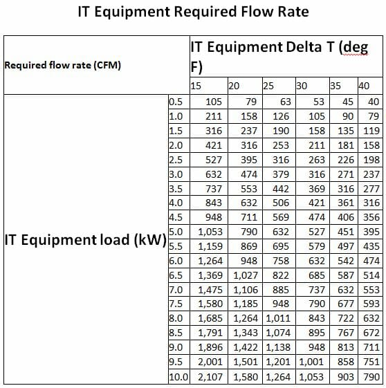
Table 1: Relationship between airflow and ΔT²
Through Cooling Units
In some cases, particularly when the conversation is being conducted among mechanical or facilities engineering participants, THE ΔT is the temperature drop across the cooling coils, or across whatever is removing the heat from the data center air, such adiabatic media or energy recovery wheel. Ideally, this delta should be the same as the delta across the IT equipment, indicating that the cooling resource is perfectly matched to the heat load it is serving. That is the ideal, but only rarely approached. First, it is useful to understand some of the design factors accounting for temperature differences across the cooling resource. Most simply, in legacy DX CRAC units, that temperature drop was typically fixed somewhere in the neighborhood of 18˚F and there was not much allowance for variation from that baseline ΔT. For example, increases in return air temperature resulted in an associated increase in supply air temperature, so a 5˚F increase in return air temperature might result in a 3˚ or 4˚ increase in the supply temperature; the overall ΔT would increase slightly, but nowhere near the proportion possible with water-cooled coils. Most of the name-brand water-cooled CRAH units today can remove heat equivalent to anywhere from 45˚ up to 65˚F temperature drop across the cooling coils. Given the mathematical relationship between heat, airflow and ΔT previously discussed (CFM = 3.1W/ΔT), the higher ΔT across those coils means we are removing more heat and therefore the CRAH unit is operating much more efficiently. Normally, we would say that is a good thing, except if the ΔT across the IT load is still only 20˚F, then we are not effectively removing any more heat; rather, we are just accommodating the inefficiency of the overall airflow management scheme.
The ΔT across the cooling source is also affected by set points. For example, if there is a lot of bypass airflow it is conceivable (this happens much more frequently than folks will admit outside the friendly confines of their local pub or tavern) that the return air can actually be below the set point and therefore is returned to the data center without any additional heat being removed: ΔT = zero. Furthermore, with a normal return set point, similar to a home or office thermostat setting, the CRAHs will be working to bring the data center temperature down to that set point, resulting in ΔT’s which could range from 0 up to over 20˚F. Finally, if the CRAHs are operating with a fixed supply temperature, the ΔT could range from 20˚-35˚ based on the types of servers deployed in that space, or the cooling coils could see less than 10˚F if there is a lot of wasted surplus cooling in the space, up to over 40˚F if there is a cumulative hot air re-circulation effect. The remaining, less discussed, two areas of ΔT can provide assistance in understanding differences between IT and coil ΔT’s and suggest possible remediating strategies.
The Less Commonly Known Delta T’s
From Cooling Unit to Front of IT Equipment
It is actually somewhat surprising that the ΔT between the cooling unit supply output and the server inlet is not on many radars. After all, if you have 55˚F being supplied, which is fairly typical, that is over 5˚F below the recommended minimum temperature for data processing equipment per the ASHRAE environmental guidelines. That low temperature is not a problem because by the time it reaches the IT equipment it is typically going to be in the 70’s, or even higher. What happens? Sometimes that supply air can warm up even before it enters the room from under the floor. For example, perforated floor tiles located too close to CRAHs can actually draw warm air into the under floor space by virtue of low pressure created by high velocity supply air – the well-known Venturi effect. That path for heating the underfloor air does not have to depend on the air velocity close to cooling units. Underfloor obstructions can create vortices which can result in low pressure pockets which can pull air from out of the room into the underfloor space, mixing with the supply air and thereby increasing the temperature before it evacuates through perforated tiles into the data center. Then, once the supply air enters the computer room, it is still subject to conditions which can further increase the temperature. If there are openings in the server racks, either open rack mount spaces or unsealed areas around the perimeter of the equipment mounting area, some of the server waste air can leak back into the cold aisle and affect the temperature of the supply air. Because of this contamination, we frequently see warmer temperatures the higher in the rack we get. Exacerbating this internal re-circulation by not receiving an adequate flow through isolated floor tiles due to low pressure zones under the floor or simply due to inadequate total available airflow volume, we can see hot air re-circulation over the tops of cabinets or around the ends of cabinet rows. The ultimate result from increasing the supply temperature along the vertical plane in front of the server rack is that the server rack inlet to outlet ΔT can be significantly higher than the equipment ΔT. For example, the temperature rise through all the servers might be 20˚F, but the inlet temperature at the bottom of the rack might be 60˚ and the outlet at the top, rear of the cabinet might be 95˚F, for a rack ΔT of 35˚, or 175% of the actual IT load.
Exhaust Back to Cooling Unit
Conversely, in most data centers today the ΔT from the servers back to the cooling source is negative; that is to say, the temperature of the return air tends to decrease after it is exhausted from the IT equipment on its return path to be re-cooled. The dynamic in this situation is very straightforward: excess cooling air is bypassing the data center heat load and returning to the cooling units, reducing the temperature of the return air along the way. There can be several causes of such bypass airflow. Improperly located perforated floor tiles (the boss gets too hot in the hot aisle) can cause cool air to bypass heat load. Large underfloor pressure differentials can result in high pressure zones that pump volumes of air into a cold aisle or portion of cold aisles in excess of the demand indicated by the intake fans of the associated IT equipment. Unsealed cable access holes in tiles located toward the rear of server racks will result in cold air directly joining the exhaust air inside the back of the server rack. This source of bypass airflow can be a little tricky when you are trouble shooting cooling efficiency issues by monitoring ΔT’s, because it can mask the true IT equipment ΔT. The simple rule of thumb here is if there are unsealed floor cut-outs in the rear of server racks, that will result in bypass and those holes should be plugged up before any other monitoring or corrective action steps are taken.
Remedial Considerations
In most situations, the optimum efficiency in the data center will be achieved when there is minimal difference between the supply air temperature and the server inlet temperature, minimal difference between the IT equipment ΔT and the cooling coil ΔT, and the supply temperature can, as a result, be elevated to a temperature approximating the maximum specified upper threshold for the space. Monitoring all four ΔT’s can provide valuable assistance for dialing in the data center to meet this optimum performance level. Any server inlet temperature that is more than 5˚F above the supply temperature being produced by cooling units means that there is hot air re-circulation caused either by open pathways between hot and cold aisle, inside or around the server racks, or there is an inadequate flow zone that may require CFD analysis to determine source of pressure variations under the floor. If the return air intake of the cooling units is more than 5˚F lower than the exhaust temperature from the IT equipment, then there is a bypass airflow problem. Areas to check include improperly placed floor tiles, unsealed floor openings, or simply excess airflow being delivered into the room.
These 5˚F guidelines for calibrating ΔT’s are merely suggestions that will help move a data center into the top 20% of efficiently and effectively performing data centers. However, the goal, particularly if free cooling is available to the data center, should be to get those differentials between the server and the cooling unit return intake and between the supply and the server intake as close to zero as possible. That alignment will result in a better harmonization between expenses made for cooling and true cooling work required, and will also increase opportunities for more free cooling hours, if free cooling is part of the total design. In conclusion, then, I’d say your goal should be to disprove my opening statement and create a space in which there is truly only one ΔT.
¹ There will be some conditions in which the ΔT will not remain constant, especially with the proliferation of variable speed fans in today’s IT equipment. When inlet temperatures are allowed to exceed the maximum recommended threshold and move toward the upper allowable levels, many servers will ramp up fans to protect the equipment, thereby reducing the ΔT through the IT equipment. Additionally, with the increased adoption of cloud-based data centers, whole large caches of work can be transferred between data centers with the resultant increased work load producing higher chip temperatures and, therefore, higher ΔT’s. Nevertheless, in normal conditions, the equipment ΔT remains a constant.

Ian Seaton
Data Center Consultant
Let's keep in touch!
Good Article, however, one important point that it should also be touch on is the IT Fan heat contribution. While it would be ‘ideal’ for the cooling unit delta-T to be the same as the Server delta-T, in a realistic world, the fan energy is also a heat source to the airstream. As a representative value many DC’s have fans operating at something near 325 Watts for every 1000 Cfm of air moved. (This is, of course, variable by DC & design point.) So a 5kW system designed & moving 790 Cfm would introduce another 257 Watts of heat & the cooling equipment needs to also remove this heat in order to meet the needs of the servers. (without accounting for the other system losses.) Now, an extra 5% of heat energy may not sound like much, but ask yourself this: how important is 1 degree F? (0.95 x 20 deg = 19 deg) To make matters worse, not all equipment manufactures account for the fan heat in the spec sheets. Sometimes – yes, sometimes – no. You need to always ask if the cooling delta-T is the “Unit” d-T, or the “Coil” d-T. As should be obvious, the “Coil” delta-T does not account for the fan heat.
Wow, Ian, scary when we are writing similar messages. I have another metric I like to match. IT load in kW –> BTU –> tons cooling load vs tonsl actually being delivered by the cooling equipment. There’s a way to calculate how many perforated tiles should be active to deliver the cooling too. To get people interested, I suggest underfloor temp of 75F and return delta t of 25F and if you don’t have that, you have savings opportunities proportional to the difference of your situation and the above. For Steve: C = (F-32)x5/9 ….. Just kidding, sort of. Dennis
Ian
Great article! Proves the logic behind air flow management philosophy with a tangible measurement method to verify your effectiveness in containment. I would assume that this logical thinking would be the basis for any Datacenter build or upgrade; custom or legacy design….however that is rarely the case from the many tours and white papers I have seen on efficiency.
This is a great article! Now if only it could be rewritten with degrees Celsius rather than degrees Fahrenheit… 🙂