What Happened to Promised Airflow Management Efficiency Savings? – Part 220 min read

This is the second half of a series on best practices for achieving airflow management efficiency savings. If you haven’t already, read the first half of the series here.
If you are operating with CRAH units and chilled water from a chiller, then you can start reaping some efficiency benefits immediately. In your baseline condition with a return set point around 70˚F plus or minus a couple degrees, your supply air was likely in the low to mid 50’s and your chilled water loop was probably around 42-45˚F. With your supply air temperature now reset to 75˚F, your chiller leaving water temperature (LWT) can be effectively increased to 65˚F. The touted resultant savings numbers are all over the map and I have heard them as high as 5% cooling cost savings per 1˚F increase in LWT. I use 1.8% per degree based on an example chart in the ASHRAE Best Practices for Datacom Facility Energy Efficiency guidebook. With that reference, this chiller adjustment of approximately 20˚F results in a 36% chiller energy savings.
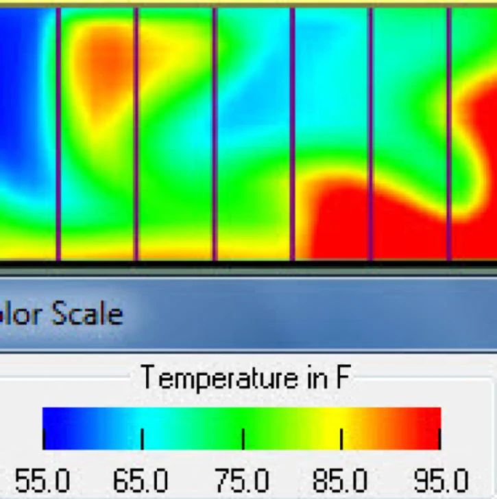
Figure 1: Server Cabinet Faces with Hot Spots
What might that mean? If your data center has an IT load around 500 kW, that is approximately 145 tons of heat load. Based on all the other non-IT load your chiller probably has to handle, plus the heat it produces itself plus a head room cushion and some level of redundancy, you should probably have 250 tons of chiller capacity. However, I am going to take a wild guess here that the guy before you sized the chiller – the same guy that did not include any airflow management in the initial deployment of your space – and he undersized at around 200 tons. Depending on brand, type and operating conditions, your chiller was costing you somewhere in the range of 0.6 to 1.2 kw per ton to operate, or anywhere from 1 million to 2 million kW hours per year. A 36% savings will bring the cost for 360,000 to 720,000 kW hours into the piggy bank for IT equipment upgrades and bonuses for managers who completed such a successful project.
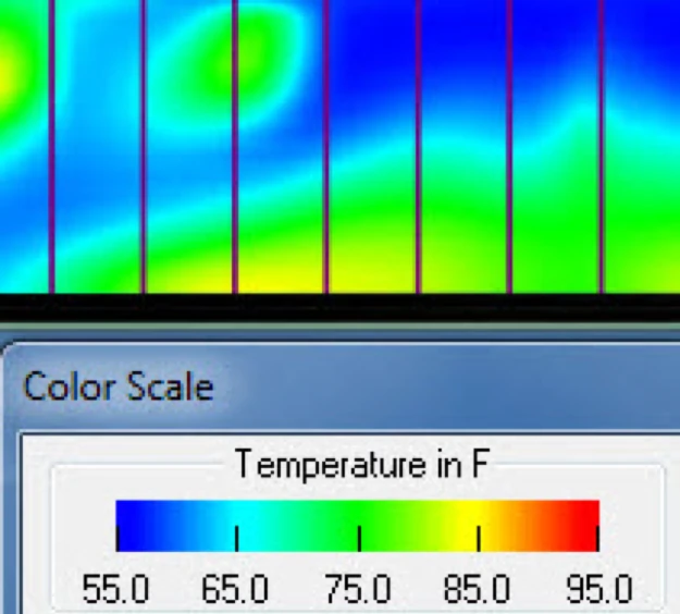
Figure 2: Server Cabinet Faces with Wide Temperature Variation
If you are cooling your data center with direct expansion cooling units, your temperature set point adjustments will be less spectacular. Nevertheless, in addition to cooling unit efficiency, you will get some additional condenser savings from a lower approach temperature based on higher condenser entering temperature.
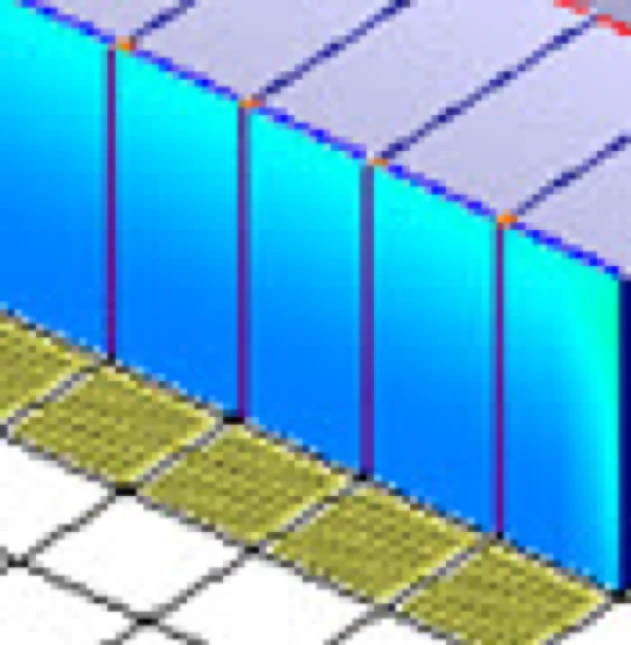
Figure 3: Server Cabinet Faces with Small Variation of Cool Temperature
Hondo, at this point your cold aisle temperature profiles should look something like Figure 5, with all your servers breathing in air somewhere around 75˚F to 77˚F and you should be pocketing significant chunks of change from your improved chiller efficiency. However, this pretty cold aisle picture is likely hiding an ugly hot aisle. With all the airflow management accessories you say you have deployed and with your new 75˚F supply set point, your hot aisles should be somewhere around 95˚F to 97˚F, plus or minus, depending on what kinds of servers you are operating, and how hard those servers are working. However, if your starting baseline condition was along the lines of Figure 3, then your hot aisle is probably 80˚F or cooler, by virtue of blasting high volumes of bypass air through your ICT equipment. If your baseline was closer to Figure 2, then your cold aisles right now will likely be around 85˚F and if your baseline was more like Figure 1, then your cold aisles could be in the 90˚F to 95˚F range. In all cases, your cooling units are now over-producing chilled air.
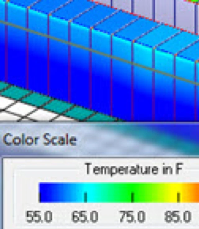
Figure 4: Server Cabinet Faces in a Cold Cold Cold Aisle
If you’ll allow me to stick with the 500 kW IT load example I started out with, then I would be guessing you had rolled out four 50 ton perimeter cooling units, to theoretically give you N+1 redundancy, but given your lack of airflow management you were running all four at full capacity and praying you didn’t ever need that +1. I suppose it’s possible that you may also be running six 30 ton units to also get you your N+1 redundancy, but since you wrote that you just had two hot aisles, it seems more reasonable that you would have four cooling units properly located at the ends of your hot aisles. You should be able to start turning down your cooling unit fan speed until your hot aisles get up into the 95˚F – 97˚F range without affecting your server inlet temperatures represented by the temperature profile in Figure 5. Now you actually have N+1 redundancy. If you do this right, by the time you get done ratcheting down your cooling unit fan speeds, you should end up with four units pushing out the same volume of air as three would at close to capacity, which means all four units are working at 75% of capacity. Since fan and pump energy are the cube of speed, our 75% fan speed means you are only using 42% of the energy these bad boys were burning up when they were running at 100% capacity, i.e., .753 = 0.4219. If your fifty ton cooling units each have three four horse power motors, then each cooling unit would be consuming around 9kW at full fan capacity, but only 3.8 kW at 75% capacity (or 42% power). Over the course of a year for the four units, you have saved another 182,500 kW hours. That, my friend, is another spot where your promised savings went.
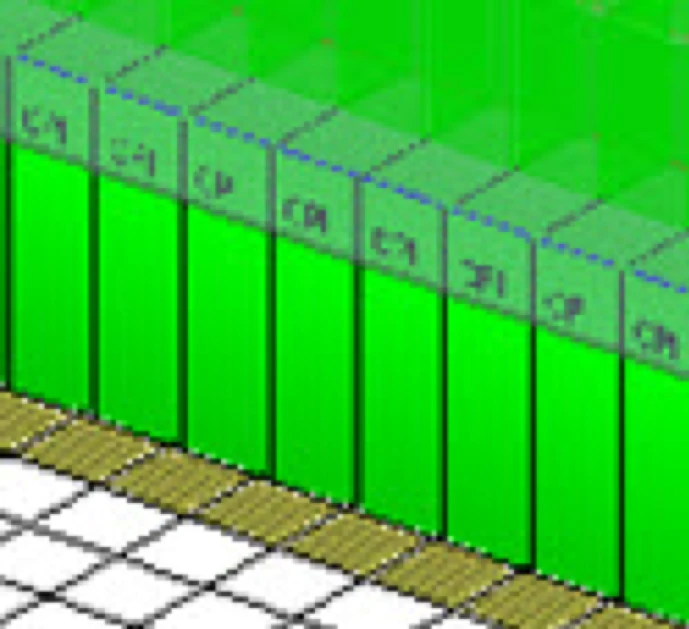
Figure 5: Server Cabinet Faces after Change to Supply Air Set Point
In the off chance you have precision perimeter cooling units without variable speed fans, your simplest path to energy savings is to turn off the extra cooling unit. Note however that your savings from this approach will be significantly less than your savings from running all four units at 75% capacity. I’ll let you enjoy the little learning exercise in setting up the problem yourself, but your answer will be that the four cooling units running with variable speed fans will use around 101,000 kW hours less electricity than running three units at full capacity. The good news is that you do not need to suffer perpetually for your predecessor’s poor judgement in cooling unit purchases. There are more than likely EC fan retrofit kits available for your cooling units and the payback is typically 2-3 years. If those units still have ten years of life in them, it’s a pretty decent investment. On the other hand, if you are running DX units, your best initial plan of action may be to just turn one off. Going forward, however, you have plenty of good choices in DX technology available to you to take advantage of your airflow management implementations. There are digital scroll DX cooling units and there are units with multiple compressors that allow you to dial in your delivered capacity along the lines of hexadecimal calculations among multiple units. The problem with older DX units was that slowing down the fans could cause the coils to freeze, but today’s technology typically allows for some fan variation and getting down to the 75% for the hypothetical case I have been building for you should be within the wheelhouse for many of them.
Finally, your new set points will allow you to take advantage of free cooling opportunities. Now Hondo, quickly before you lose your standing of civil inquiry and step on to the full-of-crap professor bandwagon because everyone knows that the climate in Kauai cannot support free cooling, let me just say, “Not so fast my friend.” True enough that even with your new set points we would need to see ambient conditions at our below 62˚F wet bulb to utilize any kind of waterside economization and the resultant 150 hours or less per year of free cooling might pay for a new coffee cup, but would hardly justify an investment in plate and frame heat exchangers and extra pipes and pumps, but airside economization or indirect evaporative cooling could be effective there in paradise. For example, your new set point should be able to get you airside free cooling for around 45% of the year. In addition, your set point should get you 40% of the year free cooling by indirect evaporative cooling, and if you adjusted your set point up a couple degrees, which still keeps your maximum below the ASHRAE TC9.9 maximum recommended temperature, you could get a little over 70% of your year covered by free cooling. For DX installations, there are dual compressor and dual coil glycol solutions that are especially suited for warm, humid climates. Granted, over time that might have to be de-rated for global warming, but the fact remains that even in your island paradise, there are viable free cooling options.
I want to thank Hondo for his letter and for giving me the opportunity to address a question that likely is ubiquitous if unstated in the far reaches of our data center community. Your promised airflow management efficiency savings did not go anywhere. If you have implemented all the airflow management best practices and you are not seeing any bottom line results, other than your servers being really cold, then you just have not finished the job. The remaining tasks are to switch from return to supply set point, raise the set point, reduce fan speeds, adjust chiller LWT, and exploit some form of free cooling. For guidelines on how to tackle this project incrementally, you can check out our article, “Six Steps to Harvest Airflow Management Returns.”

Ian Seaton
Data Center Consultant
Let's keep in touch!
0 Comments