Effects of Data Center Bypass Airflow17 min read

Remember when bypass airflow in a data center was a sign of prestige? That social marker started going the way of arsenic-induced pale complexions, corseted tiny waists and some of the more over-the-top displays of conspicuous consumption, around the time when the term was coined, and data center meat lockers started gaining pejorative status. Today, everybody within sniffing distance of a data center knows that bypass airflow, whatever that may be, is a bad thing and probably wasteful. Knowledge, however, is rarely, if ever, the same as action. For example, the guy who fell out of a 20th-floor window likely has some knowledge about the wisdom of that action – but that knowledge won’t minimize the eventual splat. Likewise, our understanding that bypass airflow is bad does not necessarily preclude our tendency to produce it still. In fact, even the data center efficiency panacea of containment is not, in fact, a fool-proof panacea for eliminating bypass airflow, though it helps a heck of a lot – wink, wink.
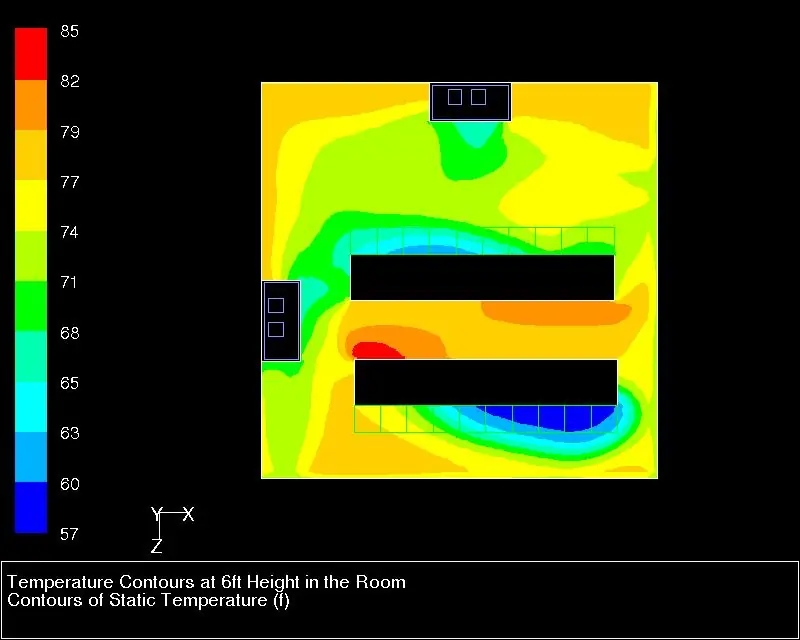
While the manifestations of bypass airflow can get complicated, we can discuss the topic intelligently with a straightforward definition: chilled air that exits the data center without having removed any heat from IT equipment or associated infrastructure – it ‘bypasses the load.’ We have discussed the causes of bypass in great detail in several other pieces in this collection, so I will not belabor that topic here. Suffice to say that bypass can take many forms and paths. Figure 1 shows bypass going around the end of a row of server cabinets resulting in return air at the cooling unit that may be at or below the setpoint. Bypass can also flow upwards out of a cold aisle and back to cooling units. Another unfortunately still too common bypass path is through floor tile cable cut-outs in the rear of server cabinets. This chilled air will increase in temperature by mixing with the exhaust air in the rear of the cabinets, but it will have done no actual work. Other possible bypass paths include improperly located supply floor tiles, improperly located cooling units, improperly spaced supply and return vents, and any number of creative circumventions, such as large box fans blowing into hot aisles to assuage worker complaints. Regardless of the path, bypass airflow results in lost cooling capacity, higher cooling costs, misleading metrics, and hot spots. Also, to avoid any social media firestorms over my alleged anti-bypass bias, I will let my readers in on a little secret later about some positive benefits of bypass airflow.
Most conversations about bypass airflow start with stranded capacity – a cooling capacity that is spinning the electric meter but not doing any work. A pretty basic textbook example of stranded capacity would cite a small data center with 60 cabinets in 6 rows with four cold aisles and three hot aisles. If we have 25% open perforated floor tiles in front of each cabinet and 6” X 9” tile cut-outs in the back of each cabinet for cable access and those cut-outs were 50% full of power and/or data cables, then we would have about eleven square feet of bypass airflow path and twelve square feet of cold aisle supply path. That means that 47.8% of the openings into the data center are delivering chilled air that is bypassing the compute heat load (11÷23).
There are a couple of directions this effect of bypass can take. For example, assuming we have a room full of 5kW server cabinets, we would need about 46,500 CFM of chilled air to remove that heat. However, since nearly 48% of our supply becomes bypass, we would need to produce 89,400 CFM to deliver 46,500 CFM into our cold aisles. That is an expensive proposition. Assuming cooling units with a maximum capacity for 17,000 CFM, four cooling units would give us N+1 cooling redundancy for the actual demand of 46,500 CFM; whereas seven cooling units would be required to deliver N+1 for the heat load and bypass. Furthermore, based on standard fan affinity laws (cube effect), our seven cooling units would be operating at 75% of rated capacity while our four cooling units would be running at 68% of rated capacity, meaning we would need seven cooling units drawing 42% of rated horsepower instead of actual demand that would be satisfied with four cooling units operating at 31% of rated horsepower. Another way of considering the same data is how the stranded capacity inhibits growth. Seven of our cooling units would produce 119,000 CFM; at N+1, six cooling units would produce 102,000 CFM which should be enough to cool a room full of 10K server cabinets. The ultimate effect of bypass airflow’s stranded capacity is that our example company would need to build a new data center equal to the current example. Well, hopefully not exactly equal.
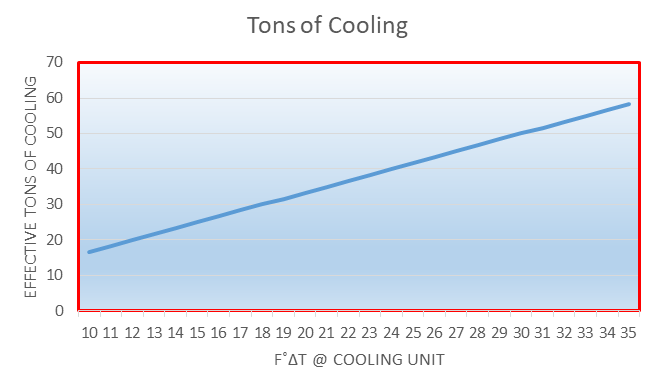
Another effect of bypass airflow is that this chilled air will mix with the chilled air that has gone to work and removed some heat from our IT equipment, thereby reducing the temperature of our return air and reducing the temperature differential (ΔT) across our cooling equipment. This temperature differential is a meaningful definition of the cooling performance of our cooling equipment; we can call it efficiency, capacity, sensible cooling and we typically measure it in tons, kW or BTU. The higher the ΔT, the more kW, tons or BTU we are effectively removing. (See my previous piece on the effects of re-circulation for exceptions). Figure 2 provides a representative example of the correlation between cooling capacity and ΔT. For this 30-ton air handler, a 6˚F reduction in the nominal ΔT means we only have a 20-ton air handler, at a 30-ton price. This lost efficiency is another aspect of the bypass airflow – the stranded capacity story.
Bypass airflow, by minimizing the difference between the supply air temperature and return air temperature across our cooling equipment, will also depress access to partial free cooling hours. In numerous previous postings, I have preached the value of elevating supply temperature to increase access to free cooling hours, but partial free cooling can also be very significant. While free cooling is categorically a misnomer, we all know what we are talking about and understand the economic value of cooling a data center without compressors and refrigerant. Whereas free cooling is based on the difference between ambient and desired maximum supply, partial free cooling is based on the difference between ambient and the return temperature. In other words, whenever the return temperature is lower than the ambient temperature (minus any approach temperature differences associated with wet bulb economizers), we are going to get at least some partial free cooling. Most economizers have this available band, and there are usually stepped values within the band; however, for a rough estimate of associated dollars, a straight line slope between compressor cooling costs (100% compressor) and free cooling costs (100% economizer) will provide a reasonable idea of what bypass is stealing. Table 2 provides some examples of lost partial free cooling hours for different cities based on the 48% bypass example developed earlier. These lost hours will vary based on the amount of bypass airflow and the temperature differentials between supply and delivered air. Where the lost hours are zero or approaching zero, it makes sense to take a good, hard look at the mechanical capacity plan: compressor-based cooling probably does not need to be scaled to carry the full load.
LOST PARTIAL FREE COOLING HOURS AT DIFFERENT SERVER INLET TEMPERATURES | ||||||
Direct Air Economizer | Indirect Evaporative Economizer | |||||
65˚F | 70˚F | 75˚F | 65˚F | 70˚F | 75˚F | |
| Atlanta | 2330 | 1528 | 931 | 2747 | 1298 | 184 |
| Chicago | 1507 | 923 | 462 | 1419 | 572 | 66 |
| Dallas | 2664 | 2029 | 1267 | 3768 | 2382 | 619 |
| Denver | 892 | 756 | 520 | 38 | 0 | 0 |
| Seattle | 389 | 158 | 42 | 26 | 0 | 0 |
Bypass airflow will also undermine the reliability of key data center metrics. A strong case can be made for using the ΔT between supply and return at our cooling equipment as the key metric for assessing the health of our data center, or at least the health of the mechanical plant. I have asserted the same on numerous occasions. For example, when that ΔT is lower than the ΔT across our IT equipment, we can safely conclude we are wasting money on bypass airflow and stranded capacity. Likewise, when that ΔT at our cooling equipment exceeds the ΔT across our IT equipment, we can be pretty sure we are re-circulating hot air through the data center and essentially re-heating it. Therefore, when those ΔT’s match up, we will think we are in pretty good shape. However, it is possible that we have significant return air re-circulation in the data center either creating hot spots or creating the potential for hot spots to pop up at the slightest change in any operational variables, but we may not go hunting for these problem areas if the ΔT across our cooling equipment is around 20˚F, or whatever we have determined the average load of the space to be.
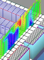
As promised, in the name of fairness, I am giving equal time to the pro-bypass crowd. Well, maybe not equal time, but at least time. Just as inadvertent or unplanned bypass airflow can mask symptoms of re-circulation problems in the data center, purposeful bypass air flow can serve to mitigate problems from re-circulation. For example, in Figure 3 we see how extra perforated floor tiles at the ends of cabinet rows, beyond the boundaries of the cold aisles, helps to ward off hot air re-circulating around the ends of the rows into the cold aisles. I have seen this technique utilized on numerous occasions to effectively solve hot spot problems. The bypass airflow is serving the same purpose as end-of-row doors.
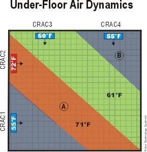
Bypass airflow can also be responsible for data center hot spots. Naturally, the previously discussed stranded capacity dynamic can cause hot spots, but a less understood relationship between bypass airflow and hot spots comes from bypass causing cooling equipment to supply warmer temperature air. This effect of bypass can result from various forms of what we call short-cycling and Figure 4 just provides an illustrative example. A couple of decades ago, when data center thermal management was beginning the transition from art to science (or maybe from superstition to science??), we learned that underfloor supply streams tended not to mix, especially at higher velocities. In this example with cooling units on adjacent walls delivering supply streams at right angles to each other, we can see how the areas of temperature influence may not be immediately predictable. We have some warmer delivered air in Zone A but we have cooler supply air from CRAC3 and CRAC1 short-cycling on the return to CRAC2 so that return air is below-set point so the CRAC knows that it doesn’t need to cool and it just sends that air back out into the raised floor area where it ends up supplying areas that are not reached by the cooler running CRAC units. Reduced set points and bypass airflow produce hot spots or at least significantly warmer areas in the data center.
My loyal readers know I have been preaching containment and supply/return separation for a couple of decades now, so it may come as a surprise to some that containment itself can be conducive to bypass airflow. How can that be? What is the one element of a containment facility that remains open between the supply side and the return side? The servers, of course. Published studies of containment research projects and experiments indicate that servers can be a conduit for significant bypass airflow. This is especially true for comatose servers, but even operating servers can have their fans over-spun by too dramatic pressure differentials between hot and cold sides. The potential for a pressure-driven bypass through the IT equipment will be greater for cold aisle containment, just by the limited available mass, so pressure differential control methodology and discipline need to become part of the overall management toolkit. The effect of this particular bypass path will be everything previously discussed.
The causes of bypass airflow are relatively well understood in the industry, and airflow management vendors offer a plethora of solutions to abate bypass airflow. A clear understanding of the effects of bypass should clarify why we spend so much time talking about causes and cures.
1 Data center temperatures shown are dry bulb temperatures, but lost partial free cooling hours for indirect evaporative cooling calculations are all based on ambient wet bulb bin data.

Ian Seaton
Data Center Consultant
Let's keep in touch!
Airflow Management Awareness Month
Free Informative webinars every Tuesday in June.
0 Comments