Data Center Cable Management and Airflow Management27 min read

Data center cable management and airflow management are not necessarily a match made in heaven, though they should be a match made somehow, somewhere. For a couple of decades, I taught courses on data center thermal management and energy conservation (popular euphemisms for airflow management). In most cities, the classes filled up with folks looking to pick up some extra continuing education credits required to maintain their industry certifications between the sizeable national education conferences. Reflecting the membership population of that organization, half or more of the attendees at these seminars were cabling contractors who, for the most part, felt excluded from anything to do with the mechanical plant or associated utility bill. Granted, our cabling friends are not part of the decision process for facility architecture, mechanical plant design, environmental service level agreements or economizer design or operation. Nevertheless, the design and execution of the physical layer directly impact the effectiveness and efficiency of the architectural layout and mechanical plant. Fortunately, cabling standards and industry best practices prescribe behaviors that support effective airflow management, with a couple of notable exceptions which I address as I step through this discussion. My thesis today is pretty straightforward. Lousy cable management practices can undermine the best airflow management plans; good cable management practices generally support good airflow management designs. Proper airflow management designs free stranded cooling capacity to support higher IT densities and enable various energy saving tactics and strategies.
My friends at Upsite Technologies trademarked the 4R methodology a few years ago to provide a roadmap for guiding efficiency upgrades in the data center: fix raised floor airflow problems first and then rack problems, row problems and finally room problems. That roadmap provides us with a useful framework for discussing the interface between cable management and airflow management, so we can start with what we do with cabling under the raised floor that either inhibits or facilitates airflow management. First, when a raised floor is deployed as a means for cooling supply air distribution, the objective is to assure the required volume of air below a required maximum temperature is delivered to a required spot in the room. That means that the ninth cabinet down row E with a 12kW actual heat load is receiving somewhere around 1860 CFM of air below whatever the specified or SLA environmental threshold determines. While such precision is not necessary for space with proper containment separating hot and cold aisles, it is de rigueur for legacy hot aisle /cold aisle spaces.
Obstacles to meeting this objective are any obstructions under the floor that will either re-direct airflow or create turbulence resulting in pockets of extreme pressure variations. While we are always amused to hear about obstacles under the floor like the company Christmas tree or a case of beer, typically these problems are caused by either cabling run amuck or cabling not planned well. I think most of us at one time or another have walked into a data center where the floor tiles wobbled when we walked on them because the volume of cable would not fit under the floor. Fortunately, the relevant standards (I’ll be referring here mostly to ANSI/BICSI 002, Data Center Design and Implementation Best Practices as it most thoroughly consolidates other TIA and EIA standards and comes explicitly out of the cabling industry) provide clear guidance on practices that facilitate meeting the raised floor airflow management objective. Specifically, underfloor pathways should run parallel to rows of cabinets and thus parallel to airflow direction. Low voltage pathways should be no deeper than 6” with the top no closer than 2” to the bottom of the floor (that is ¾” in TIA 942), and the cable trays should be designed to be filled to no more than 50% capacity. Data cabling should be in the hot aisle, and power cabling should be in the cold aisle, and they should also be vertically separated with conduit running close to the underfloor slab. Where the raised floor contains power cables, data cables, and supply air, this topology serves to minimize turbulence, vortices, pressure differentials, and uneven delivery through the perforated tiles. Uneven supply air delivery results in either hotspots or significant bypass as supply volume is over-produced to meet requirements of otherwise underserved areas.
Cable management and airflow management in the cabinet are a little more complicated and offer examples of cable management and airflow management best practices being somewhat in conflict. The objectives of airflow management in the cabinet are to prevent bypass airflow and prevent hot air re-circulation. One element of cable management at the rack level is cable ingress through the raised floor. The standards are clear: tile cut-outs under the cabinet should be as small as possible and then should be sealed around cables after they are installed. When these openings are too large or are left unsealed, they represent paths for bypass airflow with two significant consequences: 1.) Cooling capacity is diverted from where it can be used, reducing the overall cooling capacity of the mechanical plant, and 2.) The ΔT across cooling coils is reduced thereby robbing efficiency and, in extreme cases, returning below-set point, resulting in warmer supply air and the likely potential for hot spots. A 6” X 9” tile cut-out ¼ full of cable will produce 22% bypass air in conjunction with 25% open perforated floor tiles. A completely open tile space under a cabinet, which I have seen more times than I can remember, with if 1/10 full of entering cable will produce 78% bypass in conjunction with 25% open perforated floor tiles or 64% in conjunction with 50% open grates. In both cases, adherence to the standards and best practices will re-capture all that stranded capacity and allow for an exponentially commensurate cooling fan energy savings (remember P=Q3, see Table 1) or a commensurate increase in IT deployment.
Fan Energy Savings from Recaptured Bypass Airflow | |||
Cable Cut-Out | Supply Tile | Bypass Airflow | Fan Energy Savings |
6X9 ¼ full | 25% perforated | 22% | 45% |
6X9 ¼ full | 50% grate | 12% | 29% |
Full tile 1/10 full | 25% perforated | 78% | 82% |
Full tile 1/10 full | 50% grate | 64% | 78% |
Another important consideration for cable management inside the cabinet is to avoid blocking the exit path for hot exhaust air to vacate the cabinet. The standards provide a keen sense of the obvious by reminding us not to block exit airflow paths with cabling, but then ANSI/BICSI 002 provides a handy table for calculating the required width of a cabinet based on cabling size and estimated counts. The standard advises us to include the cabling plan and these resultant calculations in the procurement specifications for new cabinets. I can say with certainty that this is hardly ever done and this lack of cooperation between the various parties often has disastrous results. These disasters may not always be of the scale of Figure 1, but a 10% impedance can still result in enough re-circulation to sub-optimize set point management or work server fans harder to overcome the extra pressure head and increase that server fan energy. Remember, P=Q3 works against us just as effectively as it works for us. The good news for any particularly unscrupulous data center operators among my readership is that this effect will improve your PUE. Any of us with enough time and enough bar napkins can come up with reasonable cabinet cable capacity calculations, but if you have better things to do, this table alone is worth the price for acquiring a copy of this standard.
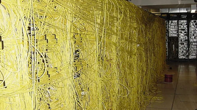
Figure 1: Result of Poor Cabinet Cabling capacity Planning
Another obstruction to airflow in the rear of equipment cabinets is the articulating cable management accessory many server OEMs provide with their rack-mounted computing equipment. The standards take a more cautious approach to these accessories by merely advising us to be aware of their potential for inhibiting good exit airflow. The fact of the matter is they cause more harm than they do good and along with the standard power cords that come with most servers, need to get recycled to wherever such flotsam goes now that China is tightening up their standards for metals. Ideally, you want all your power cords to be the shortest that will reach from the server to a vertical power strip in the cabinet. For folks concerned about being able to slide out a live server for service, make sure your technician’s rolling workbench has a longer cable which can be connected to one of the redundant power supplies to allow the server to slide forward. Buy the longer cable so you will sleep better at night, but as a matter of practice, the need will likely never arise for most of us. In addition, during the cabling planning phase before writing procurement specifications, it is a good idea to plan what length of data cables will be required, especially for top-of-rack switching installations. Specify short cables.
Switches provide a variety of cable management challenges related to the overall health of the airflow management discipline for the data center. Large switches can be particularly problematic due to the volume of cable and frequency of deploying non-compliant airflow directions. The guiding principles are the same for all in-cabinet management strategies: do not allow a cable to block cooling air intake and do not allow cabling to obstruct hot exhaust air evacuation, and maintain hot aisle and cold aisle separation. One variety of large switches requires all cable to be routed to one side to avoid interfering with hot-swappable fan kits and most of the cooling air inlets are on the same side of the cabinet as the cable routing. Without special in-cabinet ducting to capture and route air to the fan intakes, it is just asking for trouble to try to deploy more than one of these big bad boys per cabinet. Even then, the large volume of cable should be wrapped into smaller bundles, which should be kept flat against the switch front side and then split in routing to rear or top of the cabinet to allow some access path into the cabinet for cooling air and avoid blocking fan intakes on the side of the switch. Large switches with side-to-side airflow that allow cable routing to both sides are a little more forgiving, but great care must still be taken to create open paths for intake air and exhaust air. The most frequent problem with these larger switches is that cabinets are specified with inadequate width and depth for cable management accessories and airflow management accessories with adequate cable or airflow capacities which do not compromise the rest of the data center’s front-to-rear airflow protocol. The equation for calculating pressure loss for fans illustrates why the attention for managing these large volumes of cables for the larger switches is so essential.
Δp = ƒ (l /dh) (ρ v2 / 2)
where
Δp = pressure loss
ƒ = friction coefficient
l = length of duct
v = velocity
dh = hydraulic diameter (4A/P)
ρ = density
The only variable over which we have any control is the hydraulic diameter, that is to say, the size of the opening we can create through or around our cabling to allow cooling air to enter the switch. Some real-life examples should serve to bring that point home.
Variables Affecting Airflow to Large Switches | ||
Cabinet Width (mm) | Cable Circumventing Ducts | Hydraulic Diameter |
700 | No | 0.98 |
800 | No | 4.4 |
700 | Yes | 4.6 |
800 | Yes | 8.4 |
The consequences of these variations in hydraulic diameter are suggested by the fan curve in Figure 2. This curve shows us the CFM a typical switch fan will be able to generate against different head pressures, which are the inverse of the pressure drops calculated above. With the substantial differences in hydraulic diameter calculated for these different conditions, we can expect significant variations in the resultant ΔP. Referring to the fan curve, we can see that a 0.2” H2O difference at 48 CFM can result in over a 50% reduction in fan throughput. Conversely, if the fans ramp up to overcome the pressure head, we pay an energy penalty. Whereas rpm differences are cubed to get energy differences, pressure differences are squared to get energy differences – not quite as dramatic, but still a non-linear penalty. Again, for the unscrupulous, this inefficiency will get you a lower PUE, at least until you burn something up.
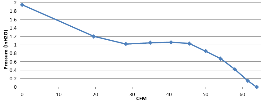
Figure 2: Performance Curve for Typical Switch Cooling Fan
Small switches have their own sets of problems with the cable management/airflow management overlap. Consensus best practices advise against locating switch cabling connections in the front of the cabinet, especially for top-of-rack switching. The impact of this cabling practice on airflow management can be disruptive, at best and destructive at worst. To keep all the cabling in the rear of the cabinet top-of-rack switches are typically installed backward on the rear mounting rails. Noticeable results are that the switches are pulling in hot air from the rear of the cabinet and the hot aisle and the switch is exhausting hot air into the cabinet at velocities that would jeopardize the inlet temperatures of the correctly mounted servers. The switch manufacturers have taken a step toward improving this long-standing issue by offering factory-set reversible fan direction. Nevertheless, the user still has a couple of essential steps to take advantage of this design improvement. First, everybody needs to be on the same page to be sure procurement has the correct specifications for fan direction. Word of caution: “front” and “back” are not particularly useful terms; port in-take or port exhaust are much more precise terms and serve to avoid costly confusion. Even better, some switches now have user configurable fan direction. With the correct fan direction established (i.e., the switch fan airflow corresponds to the other equipment in the cabinet), there remains an issue giving the switch access to supply air. The switch is mounted on the rear rails with port exhaust, which means it is pulling in “cooling” air from inside the cabinet – by definition part of the hot aisle. This situation can be corrected by adding a rack-mounted duct accessory to bridge from the switch in-take face to the cold aisle, as illustrated in figure 3. Similar accessories will accommodate switches with side inlets or side exhausts.
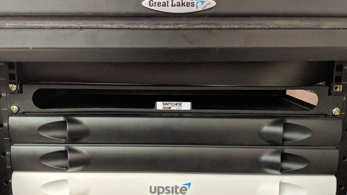
Figure 3: Example Accessory to Supply Air to Rear-Mounted Switch
The objectives of row airflow management are the same as those for cabinet airflow management: minimize bypass airflow and minimize hot air re-circulation. Cabling plays into this dynamic when it is being routed overhead rather than under the floor. ANSI/BICSI 002 covers everything we need to consider in one succinct sentence: “Care must be taken in placement of overhead cabling to ensure that return air flow is not obstructed.” The first implication of this directive is, once again, that everybody needs to be in on the planning conversation, so no mechanical design decision paints the physical layer into a non-compliant corner with no extraction re-do budget. At its purest, all the cooling equipment would be on one wall, and the ladder rack or basket tray would align with the cabinet rows, and right angle pathway would be along the wall opposite the cooling equipment. In reality, that perfect design is not always practical, and possible compromises can be assessed with computational fluid dynamics (CFD) to determine the least disruptive choice. Elevation of pathway above cabinets can help with hot and cold aisle separation as well as power distribution busbars, and CFD can help dial in the optimum elevation. Naturally, full containment or even partial containment with a return air path above the ceiling removes most of the need for mechanical precision in the cable pathway layout.
The airflow management objective at the room level is merely to provide an environment that maximizes the achievement of raised floor, rack and row objectives. While there are many airflow management considerations at the room level for maximizing the effectiveness of the lower level R’s and optimizing the efficiency of the mechanical plant and driving down the operating energy budget, the cable management contribution at the room boundaries is simple and straightforward: wherever cable is penetrating walls that separate the data hall from the rest of the building or the outside world, seal those openings around the cable. Such holes can allow bypass airflow to escape the room, reducing the available cooling capacity, reducing ΔT’s across cooling equipment, and reducing access to partial free cooling hours. Firestop requirements take care of many of these holes, and standard data center brush grommets address those penetrations not mandated by fire stop codes.
It is well known that mechanical engineers and IT staff mostly speak different languages and I have filled many pages and many hours of conference podium time trying to help bridge that gap. As for the mechanical/facilities team and the physical layer designers and installers, they may never have occasion to interact, which is an unfortunate and often costly pattern of behavior. ANSI/BICSI 002 addresses the need for these conversations in its guidelines for planning cabinet cable management and pathway layout:
- Plan equipment, power strip, cable manager, and cabling layouts in cabinets before making a significant purchase. Either create detailed drawings or preferably create a mock-up to ensure that:
- All equipment and cable managers fit correctly
- There is adequate space and access to power strips
- There is adequate access to cabinet floor and top openings
- There is adequate space for cable management
- Equipment can properly slide in and out as required
- Equipment intakes and exhausts are not blocked by cabling, cable management, or cabinet structure so that air can flow freely within the rack and exit out the hot side
- Cabinets, racks, and vertical management do not have large openings for recirculation of air from hot to cold aisles.
- Planning of overhead cable trays for telecommunications cabling should be coordinated with architects, mechanical engineers, electrical engineers, and plumbing and structural engineers that are designing luminaries, plumbing, HVAC, power, and fire protection systems. Coordination should include routing, clearances, and accessibility – consider the use of three-dimensional drawings to simplify coordination.
It always makes good sense for all disciplines to be at the table for data center planning. After all, you would not want a real estate decision to miss by 20 miles the opportunity to build without any data floor air conditioning. You would not want to undersize your UPS delivery by half and lose all that IT capacity. You would not want cabinet or server or switch purchasing decisions to cost you 50% of your potential free cooling hours every year. Likewise, all design or upgrade project plan objectives can be both raised and met by involving those responsible for the cable management plan and execution in overall plan development at the beginning.
The industry's easiest to install containment!
AisleLok® solutions are designed to enhance airflow management,
improve cooling efficiency and reduce energy costs.
The industry's easiest to install containment!
AisleLok® solutions are designed to enhance airflow management,
improve cooling efficiency and reduce energy costs.

Ian Seaton
Data Center Consultant
Let's keep in touch!
0 Comments