How to Maximize the Effectiveness of Aisle Containment in Situations With Non-Compliant Airflow Patterns25 min read

Data center airflow containment is not only a documented best practice in all data center standards; it is now legislatively mandated by some state and municipal building and energy codes. Nevertheless, containment is still not as ubiquitous as the EIA rack. While there are a variety of reasons for some remaining industry intransigence, cost and ineffectiveness are not defensible. Airflow containment will always provide a data center environment that can support higher power densities and lower energy costs and will always pay for itself relatively quickly. Sometimes these reasons may just be excuses laying over a general antipathy toward change, effort or knowledge acquisition. More often, however, I suspect they are cited when confronted with cold, hard reality which may not be as tidy as textbook installations illustrated in conference presentations, data center certification courses, magazine articles, or blogger pontifications. Reality often includes apparent barriers to optimum airflow management such as physical, mechanical or hardware complexities or obstacles. The fact is, unless we are talking about a new design that has had active involvement from IT, facilities, architectural engineering and strategic planning from the very beginning, there are going to be complexities and obstacles not accounted for in the theoretical vision of containment.
In past blogs, I have addressed obstacles to effective airflow management presented by fire suppression systems and associated codes as well as by installed mechanical infrastructure not normally associated with reaping the economic and performance benefits of containment – i.e., single speed fans and DX coolers. I have explored the confrontation with overhead physical obstacles such as ductwork, ladder rack, power busway, basket tray, or any variety of hanging Unistrut-type configurations. I’ve also discussed spaces with no raised floor and no suspended ceiling – a situation frequently interpreted as specifically designed to thwart intelligent airflow management. In all these cases, I showed how data center airflow containment could be effectively deployed and provided some guidance on how to estimate financial paybacks from set point management and airflow volume control.
In these previous blogs on overcoming obstacles to containment, all the obstacles arose from physical elements of the building or capabilities of the installed mechanical infrastructure; however, even in a perfect situation where none of those external obstacles are present, we can still undermine any plans for realizing the economic and performance benefits of airflow containment by the electronic equipment we deploy in racks and cabinets. Over the years I have regularly heard the frustration of facilities engineers and architects over their plans for creating a low PUE data center being undermined by the introduction of ICT equipment that “breathes” in some pattern other than front-to-rear. I had likewise heard of complaints from IT managers that promised containment results were not being achieved when they had deployed equipment with non-standard breathing patterns. Others have just cited the presence or planned deployment of non-standard breathing equipment as the basis for how they were unique and special and therefore not candidates for an airflow management strategy. While it is true that there is no factor more important to effective airflow management than populating the data center with equipment that breathes front-to-rear, non-conforming equipment does not need to mandate an under-performing data center. All rack-mounted equipment, regardless of where it pulls in cooling air and exhausts out waste air, even back-to-front breathing equipment, can be converted to effective front-to-rear breathing, with minimal effect on ROI and payback times.
First, it is a mistake to assume that just a few pieces of non-conforming equipment representing a small fraction of a data center is IT load will not have a significant effect on the overall performance of the data center. A relevant example can be shown in a moderately sized data center of an east coast pharmaceutical company where a small entrance room prevented the facility from realizing the efficiency results achievable by the overall room. A comparison of the open racks in a caged entrance room to enclosed chimney cabinets in the same cage is illustrated in the CFD reports in Figure 1 below. This data center consisted of 79 racks and cabinets comprising a little over 500kW IT load. The original entrance room cage included six two post racks with switches. In the model on the left in Figure 1, we can see the switches on the center pair of racks are getting inlet temperatures somewhere between 80-85˚F. To accomplish that not-quite-satisfactory level of cooling, the supply temperature to the data center was set around 55˚F, and five cooling units supplied 82,500 CFM to meet a demand for 67,500 CFM. The model on the right shows the entrance cage with the switches in chimney cabinets and the surrounding air is all about 75˚F. In this scenario, supply temperature was set at 75˚F, and the five cooling units supplied 72,000 CFM or nearly 13% less than was required by the data center with six open racks. The 13% reduction in fan demand, because of fan affinity laws, actually equates to nearly 31% reduction in fan energy. The supply air temperature adjustment resulted in saving 1,138,800 kW hours on the chiller, and the fan energy savings were about 123,000 kW hours. This data center was not utilizing any free cooling, but if it had been for its location, the set point adjustment would have resulted in an additional 3122 hours of wet bulb free cooling or 3352 hours of dry bulb free cooling.
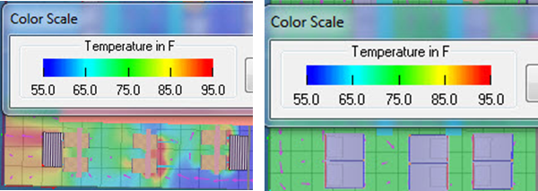
Those six open racks in a data center otherwise contained either with chimney cabinets or hot air containment aisles were preventing this data center from realizing anywhere from 1.5 – 1.6 million kW hours of energy expense cost avoidance. In fact, based on the CFD analysis, the two center racks were pushing the boundaries of acceptable inlet temperatures, so efficiently, 2.5% of the racks and cabinets and 1.9% of the total UPS load was unnecessarily raising the entire data center PUE by over .3.
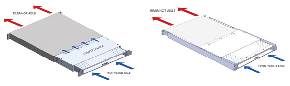
The thousand pound gorilla, and a classic example of non-compliant data center airflow equipment, is the large core switch, as illustrated in Figure 2 below. Users of these products understand all-too-well the driver for non-compliant airflow, but for the uninitiated reader let me point out that it is relatively straightforward: for managing our network connectivity we want access to the maximum number of ports in the minimum number of rack mount units, which means the switch manufacturers have had to respond with alternate airflow paths.
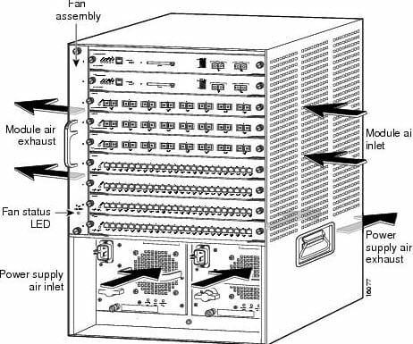
Historically, these switches have been deployed in open racks and have dramatically disrupted the airflow management of their immediate environment and negatively affected the overall operational efficiency of their host data centers. For quite a few years now users have had access to special network cabinets designed to accommodate these switches and redirect the airflow to eliminate that disruption. These cabinets will have a wider footprint than typical server cabinets for baffles, ducts, and spaces to manage inlet and exhaust air to functionally transform the subsystem into a front-to-rear breathing element. These cabinets will also typically have a higher price tag than standard server cabinets, though that delta is inconsequential regarding the cost of the switches and the impact on the data center energy budget.
While it is always preferable to house these switches in network cabinets conducive to cabinet (chimney) or aisle containment, there are going to be those times where switches have been installed on open racks, and it is just not feasible to take the network down to reconfigure everything into enclosed cabinets. Fortunately, in such cases, it is not necessary to entirely miss out on all the benefits of containment. Figure 3 below illustrates the results achievable with a little creativity in a space with side-breathing switches installed on open racks.
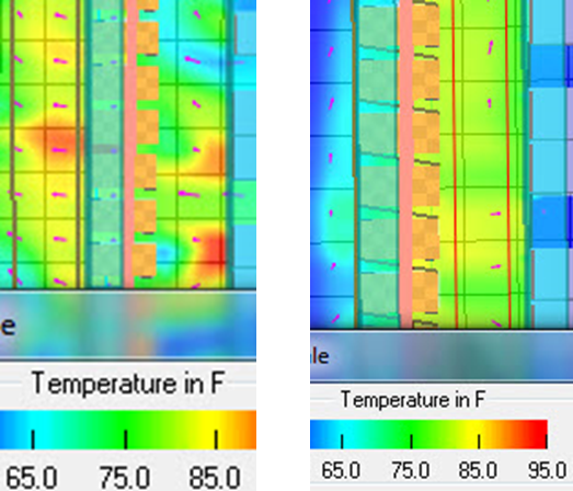
This data center had a degree of containment provided by plastic curtains hanging from the overhead supply ductwork, but there were three different areas of multiple racks with side breathing network equipment. In the before view on the left, we can see what is supposed to be the cold aisle to the left of the row of open racks, with temperatures in the 80’s and one higher temperature hot spot. The model on the right reflects the addition of sheet metal barriers between the racks, positioned diagonally to provide more isolated paths for the inlet air and exhaust air. The thermal separation between the hot aisle and the cold aisle is much more obvious. While this solution does not represent optimum separation, it is adequate to minimize the negative effect on the benefits realized from the overall containment strategy.
The big switches are obviously not the only offenders in introducing non-compliant airflow patterns into the data center. Smaller network equipment frequently deployed as top-of-rack switching clearly disrupts airflow and temperature management at the cabinet level, and, as I’ve shown in some of the earlier examples, a single problem cabinet can dramatically undo all the good intentions of an otherwise well-designed space. Top-of-rack non-compliant airflow can be introduced by the switch manufacturer in terms of side-to-side breathing, side-to-rear breathing or back-to-front breathing, as illustrated in Figure 4 below. All these iterations of non-compliance can be addressed by simple rack-mount boxes that provide paths for redirecting inlet air and exhaust air, so the cabinet and the data center see these components as front-to-rear breathing.
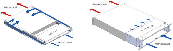
Likewise, airflow non-compliance can be introduced by us in how we install these top-of-rack switches. In order to facilitate cabling, there are switches that we may either choose to install in the cabinet backward or install in the cabinet on the rear mounting rail, thereby recessing the cold air fan inlet face behind the cabinet barrier between the cold aisle and the hot aisle. In either case, as illustrated below in Figure 5, rack mount accessories are available to either reverse the effective airflow or bridge the gap between a rear-rail-biased piece of equipment and that internal barrier between the hot aisle and the cold aisle.
There is also a variety of mass storage that comes standard in a custom cabinet with all the heat exhausted by a top-mounted fan tray. Some fifteen years ago in one of my first public data center seminars titled, “Everything You Know about Data Center Cooling Is Wrong,” one of the tidbits of conventional wisdom I debunked was the value of cabinet top-mounted fans. I reported on empirical testing and third-party CFD modeling that clearly showed how these configurations actually caused hot spots. Fast forward to a time when aisle separation and hot and cold air containment are minimum requirements for data center mechanical effectiveness and efficiency, and it is clear how these top exhausting systems undermine any efforts at intelligent airflow management. Fortunately, there are ways to integrate this equipment into a space with airflow containment. The rack-mount storage equipment can be transferred to a server cabinet equipped with a chimney to maintain hot air isolation. Also, hot air containment aisle barriers can be extended to the back side of cabinets in a row with the storage rack to capture all the hot exhaust air and rout it into the standard airflow path, or a cold air containment aisle roof could terminate at the front edge of the storage equipment rack to rout all the exhaust air away from the contained cold aisle.
In the past, equipment that did not breathe front-to-rear or front-to-top interfered with the effectiveness of basic hot aisle-cold aisle separation. With the increased emphasis on such separation through aisle containment, this non-compliant equipment or our non-compliant way of deploying some equipment, does not mean we need to sacrifice the effectiveness and efficiency benefits of containment. Many of these standard product solutions to airflow problems were originally one-off solutions for some engineer whose commitment to intelligent airflow management was not going to be derailed by a single non-compliant rack. With that spirit and a good track record of solving these problems, I cannot imagine a component of IT or network equipment that could not somehow be integrated into a good containment plan.
The industry's easiest to install containment!
AisleLok® solutions are designed to enhance airflow management,
improve cooling efficiency and reduce energy costs.
The industry's easiest to install containment!
AisleLok® solutions are designed to enhance airflow management,
improve cooling efficiency and reduce energy costs.

Ian Seaton
Data Center Consultant
Let's keep in touch!
0 Comments